
1. Uvod i krajview
The DollaTek CJMCU-5351 Si5351A Clock Generator Breakout Board is an I2C-controlled device designed to generate precise and arbitrary frequencies. It utilizes an integrated 25 MHz crystal reference and internal Phase-Locked Loops (PLLs) to produce frequencies ranging from 8 KHz to over 150 MHz. This board offers three independent clock outputs, each configurable to a different frequency. It is compatible with 3V to 5V DC power supplies and includes I2C level shifters for seamless integration with both 3V and 5V logic microcontrollers.

Image 1.1: The DollaTek CJMCU-5351 Si5351A board, showing the main chip, 25MHz crystal, and output pins with optional SMA connectors.
2. Ključne karakteristike
- Crystal Reference: Integrated 25 MHz crystal for high precision.
- Frekvencijski raspon: Generates frequencies from less than 8 KHz up to 150+ MHz.
- Kontrolni interfejs: I2C controller for easy configuration.
- Izlazni kanali: Three independent clock outputs (CLK0, CLK1, CLK2), each configurable to a different frequency.
- Output Voltage: 3Vpp signal level.
- Napajanje: Operates from 3V to 5V DC, thanks to an onboard 3.3V LDO regulator.
- Logic Compatibility: I2C level shifting circuits ensure compatibility with both 3V and 5V logic microcontrollers.
- Povezivanje: Outputs available via breadboard-compatible header pins or optional SMA connectors for RF applications.
3. Upute za postavljanje
Follow these steps to set up your CJMCU-5351 Si5351A Clock Generator Breakout Board:
- Priključak za napajanje: Connect your 3V to 5V DC power source to the VIN pin and ground to the GND pin on the board. Ensure correct polarity to prevent damage.
- I2C Interface Connection:
- Povežite SCL pin on the Si5351A board to the I2C clock line of your microcontroller.
- Povežite SDA pin on the Si5351A board to the I2C data line of your microcontroller.
- The board's integrated level shifters allow direct connection to both 3V and 5V logic systems.
- Priključak izlaza sata: Connect your target circuit to the desired clock output pins: CLK0, CLK1, ili CLK2. These outputs provide a 3Vpp signal. For radio frequency (RF) applications, optional SMA connectors can be soldered to the board for more robust connections.
- Podešavanje softvera: Install the appropriate library for the Si5351A chip on your microcontroller's IDE (e.g., Adafruit Si5351 library for Arduino). This library provides functions to initialize the chip and configure its outputs.

Slika 3.1: Detaljno view of the Si5351A board showing pin assignments for power, I2C communication, and clock outputs.
4. Uputstvo za upotrebu
The Si5351A clock generator is controlled via the I2C interface. Once the board is powered and connected to your microcontroller, you can program it to generate specific frequencies.
- Inicijalizacija: In your microcontroller code, initialize the I2C communication and the Si5351A library. This typically involves calling an initialization function provided by the library.
- Konfiguracija frekvencije: Use the library functions to set the desired frequency for each of the three clock outputs (CLK0, CLK1, CLK2). The Si5351A uses internal PLLs and dividers to synthesize frequencies. For example, a function call might look like
si5351.set_freq(10000000, SI5351_CLK0);to set CLK0 to 10 MHz. - Kontrola izlaza: You can enable or disable individual clock outputs as needed through software commands.
- Arbitrary Frequencies: The Si5351A is capable of generating a wide range of arbitrary frequencies with high precision. Refer to the specific library documentation for detailed examples and advanced configuration options, such as setting PLL multipliers and divider ratios.
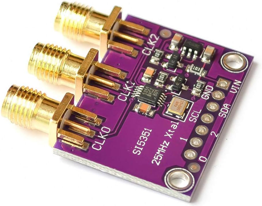
Image 4.1: Component layout of the Si5351A board, highlighting the main Si5351 chip and the 25MHz crystal.
5. Održavanje
The DollaTek CJMCU-5351 Si5351A board requires minimal maintenance. Adhering to the following guidelines will help ensure its longevity and reliable operation:
- čistoća: Keep the board free from dust, dirt, and debris. Use a soft, dry brush or compressed air for cleaning.
- Zaštita od vlage: Avoid exposing the board to moisture or high humidity, which can cause short circuits and corrosion.
- temperatura: Operate and store the board within its specified temperature range. Avoid extreme heat or cold.
- statičko pražnjenje: Handle the board with care, especially in environments prone to static electricity. Use anti-static precautions when handling.
- Veze: Periodically check all electrical connections (power, I2C, outputs) to ensure they are secure and free from corrosion.
6. Otkrivanje problema
If you encounter issues with your DollaTek CJMCU-5351 Si5351A board, consider the following troubleshooting steps:
- No Output or Incorrect Frequency:
- Proverite da li je napajanje voltage is within the 3V to 5V DC range.
- Check all I2C connections (SDA, SCL, GND) for proper wiring and continuity.
- Review your microcontroller code to ensure the Si5351A is correctly initialized and the desired frequencies are being set.
- Confirm the correct I2C address for the Si5351A chip (typically 0x60).
- Ensure the output pins are correctly connected to your measurement device or target circuit.
- Board Not Detected by Microcontroller:
- Double-check power and ground connections.
- Inspect I2C lines for any shorts or open circuits.
- Confirm that your microcontroller's I2C bus is properly enabled and initialized in your software.
- Test with a simple I2C scanner sketch to confirm the board's presence on the bus.
- Nestabilan izlaz:
- Ensure a stable and clean power supply. Noise on the power line can affect clock stability.
- Check for external electromagnetic interference (EMI) that might affect the board.
- Verify that the crystal on the board is securely attached and undamaged.
7. Specifikacije
| Feature | Specifikacija |
|---|---|
| Proizvođač | DollaTek |
| Naziv modela | CJMCU-5351 |
| Čipset | Si5351A |
| Crystal Reference Frequency | 25 MHz |
| Izlazni frekvencijski raspon | 8 KHz do 160 MHz |
| Izlazni kanali | 3 independent (CLK0, CLK1, CLK2) |
| Nivo izlaznog signala | 3Vpp |
| Ulazni voltage | 3-5VDC |
| Tehnologija povezivanja | I2C |
| Logic Compatibility | 3V and 5V (with onboard level shifters) |
| Kompatibilni uređaji | Microcontrollers and development boards with I2C support |
| UPC / GTIN | 742548987367 |
8. Garancija i podrška
Specific warranty information for this product is not provided in the available documentation. For technical support, product inquiries, or warranty claims, please contact DollaTek customer service directly. Additionally, extensive community support and documentation for the Si5351A chip are available online, which can be a valuable resource for advanced usage and troubleshooting.